| |
| |
Caption: Dedication - Locomotive Testing Laboratory (1913)
This is a reduced-resolution page image for fast online browsing.
EXTRACTED TEXT FROM PAGE:
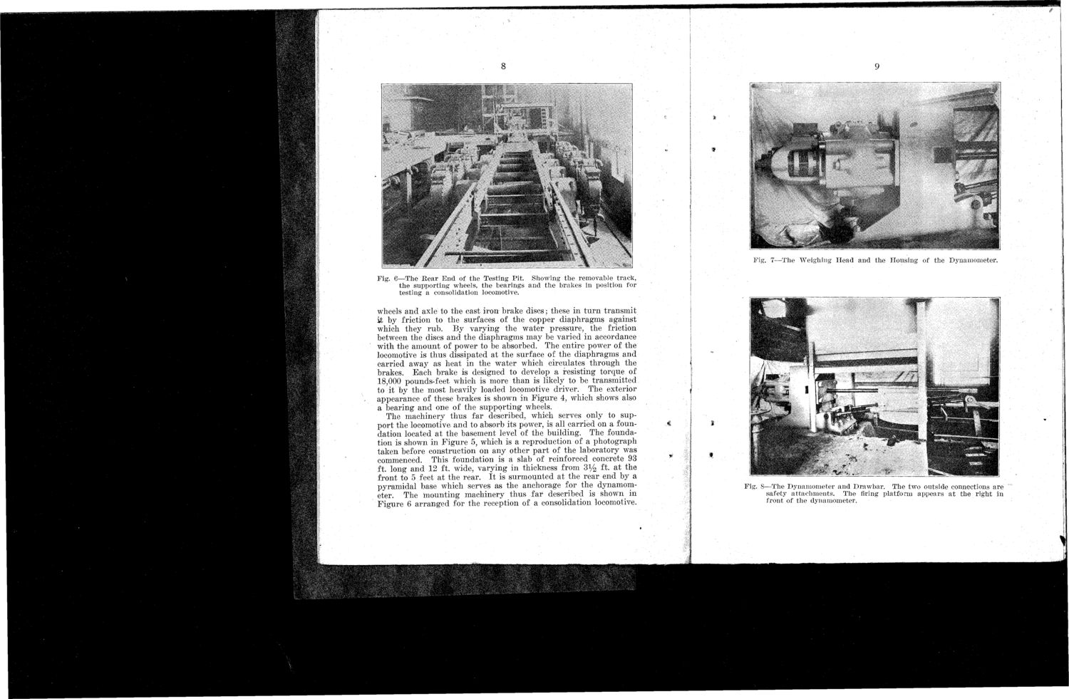
8 Fig. 7—The Weighing Head and the Housing of the Dynamometer. Fig. 6—The Rear End of the Testing Pit. Showing the removable track, the supporting wheels, the bearings and the brakes in position for testing a consolidation locomotive. wheels and axle to the cast iron brake discs; these in turn transmit it by friction to the surfaces of the copper diaphragms against which they rub. By varying the water pressure, the friction between the discs and the diaphragms may be varied in accordance with the amount of power to be absorbed. The entire power of the locomotive is thus dissipated at the surface of the diaphragms and carried away as heat in the water which circulates through the brakes. Each brake is designed to develop a resisting torque of 18,000 pounds-feet which is more than is likely to be transmitted to it by the most heavily loaded locomotive driver. The exterior appearance of these brakes is shown in Figure 4, which shows also a bearing and one of the supporting wheels. The machinery thus far described, which serves only to support the locomotive and to absorb its power, is all carried on a foundation located at the basement level of the building. The foundation is shown in Figure 5, which is a reproduction of a photograph taken before construction on any other part of the laboratory was commenced. This foundation is a slab of reinforced concrete 93 ft. long and 12 ft. wide, varying in thickness from 3y2 ft. at the front to 5 feet at the rear. It is surmounted at the rear end by a pyramidal base which serves as the anchorage for the dynamometer. The mounting machinery thus far described is shown^ in Figure 6 arranged for the reception of a consolidation locomotive. Fig. 8—The Dynamometer and Drawbar. The two outside connections are safety attachments. The firing platform appears at the right in front of the dynamometer.
| |