Caption: Dedication - Locomotive Testing Laboratory (1913)
This is a reduced-resolution page image for fast online browsing.
EXTRACTED TEXT FROM PAGE:
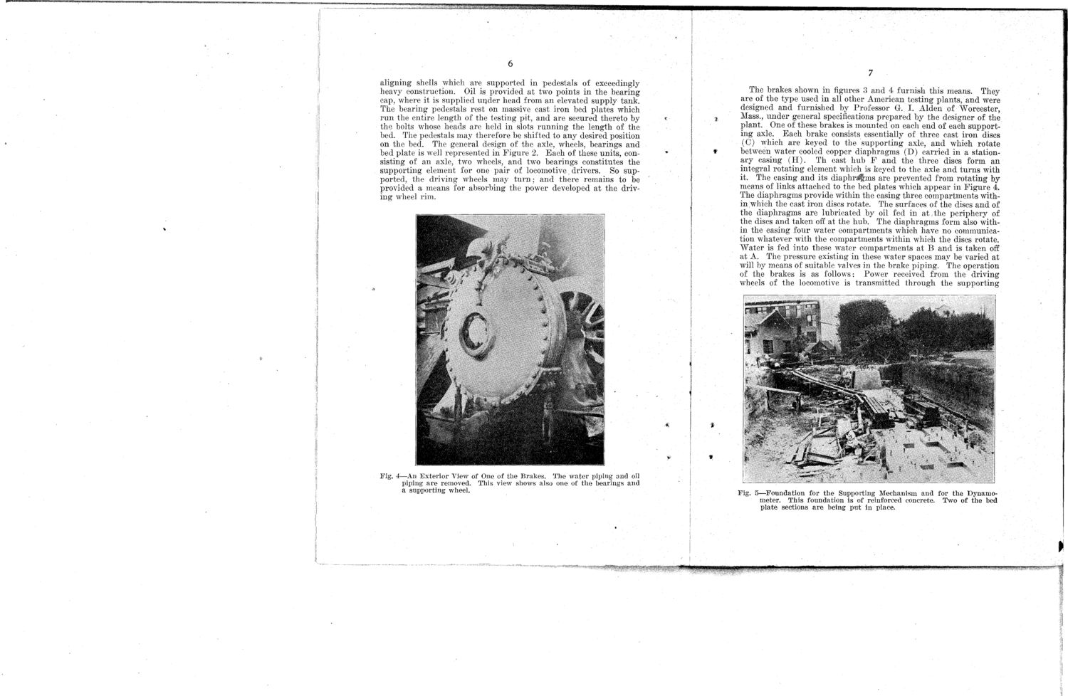
6 aligning shells which are supported in pedestals of exceedingly heavy construction. Oil is provided at two points in the bearing cap, where it is supplied uijder head from an elevated supply tank. The bearing pedestals rest on massive cast iron bed plates which run the entire length of the testing pit, and are secured thereto by the bolts whose heads are held in slots running the length of the bed. The pedestals may therefore be shifted to any desired position on the bed. The general design of the axle, wheels, bearings and bed plate is well represented in Figure 2. Each of these units, consisting of an axle, two wheels, and two bearings constitutes the supporting element for one pair of locomotive\ drivers. So supported, the driving wheels may turn; and there remains to be provided a means for absorbing the power developed at the driving wheel rim. 7 The brakes shown in figures 3 and 4 furnish this means. They are of the type used in all other American testing plants, and were designed and furnished by Professor G. I. Alden of Worcester, Mass., under general specifications prepared by the designer of the plant. One of these brakes is mounted on each end of each supporting axle. Each brake consists essentially of three cast iron discs (C) which are keyed to the supporting axle, and which rotate between water cooled copper diaphragms (D) carried in a stationary casing ( H ) . Th cast hub F and the three discs form an integral rotating element which is keyed to the axle and turns with it. The casing and its diaphrJfms are prevented from rotating by means of links attached to the bed plates which appear in Figure 4. The diaphragms provide within the casing three compartments within which the cast iron discs rotate. The surfaces of the discs and of the diaphragms are lubricated by oil fed in at the periphery of the discs and taken off at the hub. The diaphragms form also within the casing four water compartments which have no communication whatever with the compartments within which the discs rotate. "Water is fed into these water compartments at B and is taken off at A. The pressure existing in these water spaces may be varied at will by means of suitable valves in the brake piping. The operation of the brakes is as follows: Power received from the driving wheels of the locomotive is transmitted through the supporting Fig. 4—An Exterior View of One of the Brakes. The water piping and oil piping are removed. This view shows also one of the bearings and a supporting wheel. Fig. 5—Foundation for the Supporting Mechanism and for the Dynamometer. This foundation is of reinforced concrete. Two of the bed plate sections are being put in place.
|