| |
| |
Caption: SWE - Proceedings of the First International Conference of Women Engineers and Scientists
This is a reduced-resolution page image for fast online browsing.

EXTRACTED TEXT FROM PAGE:
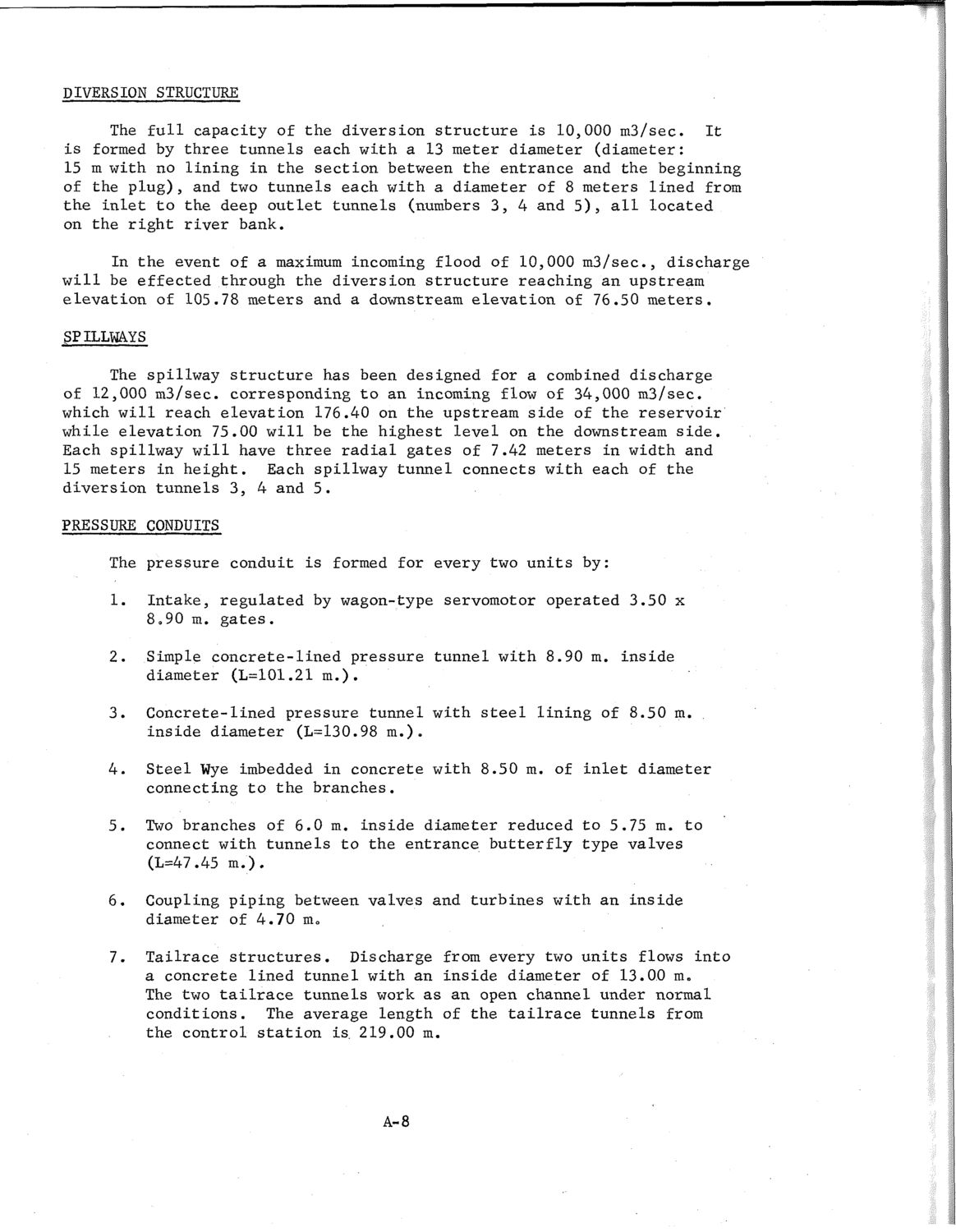
DIVERSION STRUCTURE The full capacity of the diversion structure is 10,000 m3/sec. It is formed by three tunnels each with a 13 meter diameter (diameter: 15 m with no lining in the section between the entrance and the beginning of the plug), and two tunnels each with a diameter of 8 meters lined from the inlet to the deep outlet tunnels (numbers 3, 4 and 5), all located on the right river bank. In the event of a maximum incoming flood of 10,000 m3/sec, discharge will be effected through the diversion structure reaching an upstream elevation of 105.78 meters and a downstream elevation of 76.50 meters. SPILLWAYS The spillway structure has been designed for a combined discharge of 12,000 m3/sec. corresponding to an incoming flow of 34,000 m3/sec. which will reach elevation 176.40 on the upstream side of the reservoir while elevation 75.00 will be the highest level on the downstream side. Each spillway will have three radial gates of 7.42 meters in width and 15 meters in height. Each spillway tunnel connects with each of the diversion tunnels 3, 4 and 5. PRESSURE CONDUITS The pressure conduit is formed for every two units by: 1. Intake, regulated by wagon-type servomotor operated 3.50 x 8.90 m. gates. Simple concrete-lined pressure tunnel with 8.90 m. inside diameter (L=101.21 m.). Concrete-lined pressure tunnel with steel lining of 8.50 m. inside diameter (L=130.98 m.). Steel Wye imbedded in concrete with 8.50 m. of inlet diameter connecting to the branches. Two branches of 6.0 m. inside diameter reduced to 5.75 m. to connect with tunnels to the entrance butterfly type valves (L=47.45 m . ) . Coupling piping between valves and turbines with an inside diameter of 4.70 m. Tailrace structures. Discharge from every two units flows into a concrete lined tunnel with an inside diameter of 13.00 m. The two tailrace tunnels work as an open channel under normal conditions. The average length of the tailrace tunnels from the control station is. 219.00 m. 2. 3. 4. 5. 6. 7. A-8
| |