| |
| |
Caption: War Publications - WWI Compilation 1923 - Article 46
This is a reduced-resolution page image for fast online browsing.
EXTRACTED TEXT FROM PAGE:
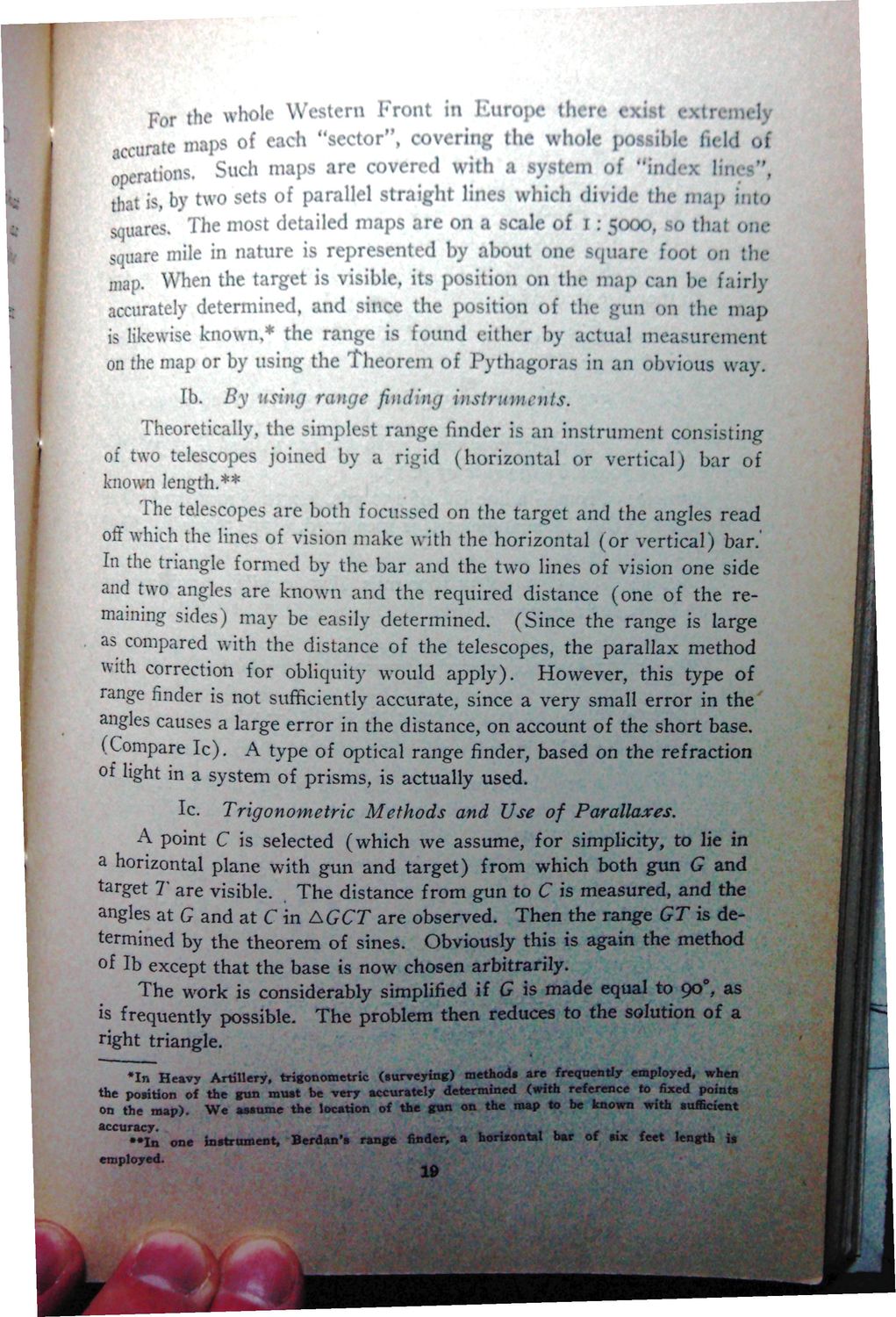
For the whole Western Front in Europe there exist extras I ccurate maps of each "sector", covering the whole jwiiible field oi «-Mtinns Such maps tre covered with a system of "index lines", squares. The most detailed maps are on a scale of I . 5000, *> that om: square mile in nature is represented by about one square foot on [inmap. When the target is visible, its position on the map can be fairly accurately determined, and since the position of the gun on the map known,* the range on the map or by using the Theorem of Pythagoras in an obvious way. lb. By using range finding instruments. Theoretically, the simplest range finder is an instrument consisting of two telescopes joined by a rigid (horizontal or vertical; bar of known length.** The telescopes are both foeussed on the target and the angles read off which the lines of vision make with the horizontal (or vertical) bar.' In the triangle formed by the bar and the two lines of vision one side and two angles are known and the required distance (one of the remaining sides) may be easily determined. (Since the range is large as compared with the distance of the telescopes, the parallax method with correction for obliquity would apply). However, this type of range finder is not sufficiently accurate, since a very small error in the angles causes a large error in the distance, on account of the short base. (Compare Ic). A type of optical range finder, based on the refraction of light in a system of prisms, is actually used. Ic. Trigonometric Methods and Use of Parallaxes. A point C is selected (which we assume, for simplicity, to lie in a horizontal plane with gun and target) from which both gun G and target T are visible. The distance from gun to C is measured, and the angles at G and at C in AGCT are observed. Then the range GT is determined by the theorem of sines. Obviously this is again the method of lb except that the base is now chosen arbitrarily. 00 possible. The problem then reduces to the solution of a ight triangle. (surrey ing) the position of the gun must be very accurately determinea iwun rcxcrcucc ro n w a points on the map). We assume the location of the gun on the map to be known with sufficient accuracy. . t , • • I n one Instrument, Berdan's range finder, a horizontal bar of six feet length is employed. 19
| |